| THERMO Spoken Here! ~ J. Pohl © | TOC NEXT ~ 225 |
Boost Pump
The schematic shows a piston/cylinder component of a hydraulic circuit. Normally the circuit operates at low-pressure. The piston is motionless and the cylinder contains its maximum volume of fluid. In this condition, hydraulic fluid pumped to the task bypasses the cylinder. Periodically, when extra "Oomph" is needed, an electrical signal shuts the one-way valve and activates the motor to drive the piston to the right.
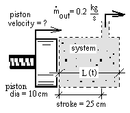
Fluid exits the cylinder at 0.2 kg/s. The density of hydraulic fluid is ρ = 800 kg per cubic meter.
Calculate the required velocity of the piston face.
♦ Obviously, we start with the mass equation.
| (1)Typical mass equation. |
The system mass equals ρAL(t). Zero fluid enters. Fluid exits the system at a rate (at the exiting boundary) of 0.2 kg/s. So...
| (2) The fluid density and piston area are constant. |
The fluid density and piston area are constant - move them out of the derivative. Apply numbers of the geometry. The piston speed can be obtained.
| (3) The piston speed can be obtained. |
Calculate the mass of hydraulic fluid delivered per stroke and time required.
Above, left of equality, is the mass delivered per stroke:
m = 1.57 kg.
Next, the equation solves for the time per stroke:
tfin = 1.57 kg/(0.2 kg/s) = 7.8 seconds.
Boost Pump
The schematic shows a piston/cylinder component of a hydraulic circuit. Normally the circuit operates at low-pressure. The piston is motionless and the cylinder contains its maximum volume of fluid. In this condition, hydraulic fluid pumped to the task bypasses the cylinder. Periodically, when extra "oomph" is needed, an electrical signal shuts the one-way valve and activates the motor to drive the piston to the right.
Premise presently unwritted!