| THERMO Spoken Here! ~ J. Pohl © | TOC NEXT ~ 170 |
Vacuum-Launched Rocket
To place scientific packages in Earth orbit is expensive. A part of the cost is the great amount of fuel consumed in liftoff. The schematic (below-right) shows a system proposed as the first, lift-off stage, of a rocket.
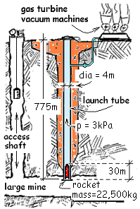 Setup: The launcher is built into a mine having at least two vertical shafts which are the supply shaft and launch shaft. The supply shaft serves as a supply passage for equipment etc, and upon firing as a duct for passage of atmospheric air. The launch shaft is constructed to have a cylindrical, steel, air-tight liner. The launch shaft has cover plates that seal the shaft at the top and the bottom.
To prepare a launch, a rocket is fitted snugly inside the launch shaft onto stops just above the bottom cover plate. The top coverplate is put into position. Next vacuum machines slowly and economically extract air from the launch shaft until the pressure of the air inside becomes 3 kilopascal throughout.
Fire and Lift-Off: Rocket Launch initiates upon explosive destruction of the bottom-cover. Atmospheric air rushes into the shaft bottom, encounters the bottom of the rocket and shoves it upward. The pressure of the air trapped above the rising rocket (initially 3kPa) increases as the rocket moves upward. The top cover is designed to "spring-open" the instant pressure of trapped-air in the shaft attains atmospheric pressure, 101.3 kPa.
Will the Rocket Move Upward?
♦ With the rocket as system, we apply Newton's Second Law of Motion, in the vertical direction. Once the bottom is removed, atmospheric pressure will act across the bottom area and 3 kPa will act over its top. If the acceleration at that instant is positive or upward, the rocket will move upward.
| (1)
Newton's 2nd Law ~ vertical cmponent. |
We have numbers for most of the terms:
| (2)
Enter known numbers! |
Thus upon "fire" (at t = 0+) the rocket will have an upward with an acceleration of 45 m/s².
When will the Top Cover Deploy?
The system of this event is the trapped-air.
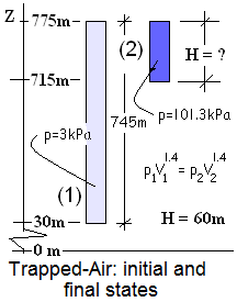
The sketch shows the initial (light blue) column of air (745 meters tall) (1). As the rocket rises, the height of the air diminishes; the trapped-air is compressed. When the trapped-air pressure becomes 101.3 kpa (dark blue) (2), the top cover deploys. We notate the column height of the second state of the trapped-air as H.
For this event, we assume the sum of heats equal to zero (ΣQ1-2 = 0). This is reasonable because all temperatures are in equilibrium initially and the event is too fast for there to be heat. The trapped-air will experience friction during its event, principally as shock waves propogating throughout. At this level of study being unable to calculate the friction effect, we are obliged to assume the event to be frictionless and adiabatic (called reversible-adiabatic by some). Of course our answer is now highly idealized. Without the assumption we get no answer at all.
Ideal Gas states of a frictionless-adiabatic process obey the equation, pVγ = constant, where γ, the ratio of specific heats of air equals 1.4 . When the rocket attains the "deploy cover" elevation, the pressure of the air above it will have attained 101.3 kPa. That elevation, H of the second state (2), is calculated, below:

| (3) 3 |
Entering numbers into Eqn(3) (right-most expression), we obtain H, as:
| (4)4 |
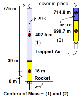 Subject to our approximations, when the top of the rocket is 60.3 meters below the exit plane of the top cover, the trapped-air pressure will be 101.3kPa, and the top cover will deploy. At that time the air pressure above and below the rocket will be atmospheric.
Calculate the Rocket Velocity.
Potential energies of the event are important. The sketch, Centers of Mass, shows the initial, (1), and final, (2), elevations of the center of mass of the rocket (modeled as a solid) and the center of mass of the trapped-air (modeled as an ideal gas).
Our event involves action of both the rocket and the trapped-air. Analysis might proceed with a two system approach. To write and solve two energy equations; one with rocket as system, the other with as trapped-air as system. Alternately a combined system, one energy equation with both masses as system might be solved.
Two System Approach: Separate systems are the rocket and the trapped-gas.
Energy Equation Rocket: Modeled as a constant temperature solid with zero-heat for the event. Work of the event occurs via atmospheric pressure at the rocket bottom and via pressure of the trapped-air at its top.
 | (5)5 |
 | (6)6 |
Energy Equation Trapped-Air: Modeled as an Ideal Gas having a frictionless, adiabatic event (zero-heat). Work of the trapped-air occurs at the bottom of the trappped-air column.
 | (7)7 |
Appendix Calculations: The mass of trapped-air is 325kg, the specific heat of air as 7/2M, and the temperature of the trapped-air, once compressed to 101.3kPa in a frictionless-adiabatic process, is 548°C. The "trapped-air" energy equation is Eqn-8.
 | (8)8 |
 | (9a)9a |
 | (9b)9b |
When triggered, the "atmosphere, rocket, and trapped air" arrangement accelerates the rocket to its launch velocity. Two components, the rocket and trapped-air experience energy interaction. Consequently (as above) we analyzed the device as two systems. Our results, to this point, are two non-linear equations, Eqn-9a and Eqn-9b.
The unknown quantity we seek is the launch velocity, v2, which appears, left of equality, in Eqn-9a. Solution would be direct were "work of the rocket," right of equality, Eqn-9a calculated. We look next at Eqn-9b; what help is there? Eqn-9b contains the unknown velocity (center of mass) of the trapped-air left of equality; no help. But, right of equality appears the "work of the trapped-air."
A "rule of thumb" in thermodynamics is: "Work is calculated as (i) a term of an energy equation or (ii) by specification and integration of its "force-displacement relation." Method (i) is easier; when possible, avoid calculation of work. With this understanding, one realizes the work of Eqn-9a and Eqn-9b are the same. Hence we add the equations. Physically, this amounts to a new system perspective. The combined equations are a single energy equation representing both the rocket and the trapped-air as a composite system.
The sketch above, "Centers of Mass" shows states (1) and (2) of the system: rocket and trapped-air. The increment form of the energy equation for these two masses as system is:
 |
(10) 5 |
Before firing, the sum of heats is zero (ΣQ = 0) because everything is in thermal equilibrium. The event is fast so we assume the sum of heats for the event to be very small, (ΣQ1-2 = 0) Next we expand the terms of the energy equation and strike out the small terms, as " /."
 | (6)6 |
As the rocket moves up the shaft, because the air above the rocket is part of the system, there is only one work effect - the pressure of atmospheric air acting over bottom area the rocket as it displaces upward. The event ends when the top of the rocket is 60 meters below the exit. We set up the work integral carefully and write the energy changes explicitly.
| (7) 7 |
The temperature difference of the air can be determined. We assumed its process adiabatic and frictionless. In a previous example (Air Pistol) the following expression for the second temperature which uses the property, γ = 7/5 (for an ideal diatomic gas) was derived. . We combine these facts to calculate the second temperature of the gas.
 |
(8) 8 |
In addition, the mass of the trapped air is needed.
 |
(9) 9 |
The numbers are entered into the equation.
 |
(10) 10 |
Applying the numbers carefully:
| (11) 11 |
Watch the units!
| (12) 12 |
That seems a rather substantial speed.. Check the numbers, please. But then this is idealized.
HS Project
The basic idea of the launching system adapts well to become a HS demonstration. Figure shows the setup.
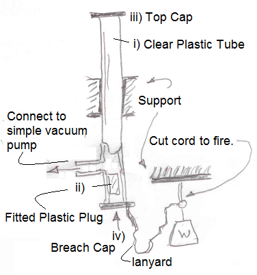
- Tube: A precision, clear glass tube works well. (say 2" ID by 40" L). Order one from a scientific supplier.
- Plug: A solid plastic plug is turned to fit the tube.
- Top Cap: Light rigid plate (aluminum).
- Breach Cap: I used a stretched, banded to cover aluminum foil (to be punctured).
- Port: A tube connects the tube to a simple vacuum pump. Include a pressure gage in the port tube.
Vacuum-Launched Rocket
To place scientific packages into Earth orbit is expensive. A great part of the cost is the fuel consumed with lift-off. The schematic shows a system proposed as the first, lift-off stage.
Setup: The tall circular launch tube is a shaft that extends downward into a large mine with numerous accesses. The rocket, positioned in the tube snugly, is supported at the bottom of the shaft. A strong, deployable hatch covers the top of the shaft and beneath the rocket, sealing the shaft below, is an explosively destructible shield. Prior to a launch, vacuum machines slowly and economically extract air from the shaft until a pressure of 3 kPa is attained.
Premise presently unwritted!