| THERMO Spoken Here! ~ J. Pohl © | TOC NEXT ~ 1 |
Otto Von Guernike
German scientist, inventor and engineer.
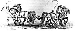
BUCK!  JAKE!
PULL!  Big Boys, Pull!
At a fair in 1654 Otto amazed the spectators. He showed them two hemispherical brass shells that fit together (to form a hollow sphere) but fell apart when not held. Next, (using the air pump he invented) Otto removed air from the inside of the sphere. Each hemisphere had built-in ring to which a rope was attached. The other ends of the ropes were attached to harnesses of two teams of horses. The horses, urged to pull, strained and snorted but, to the surprise of everyone, they were unable to pull the hemispherical shells apart.
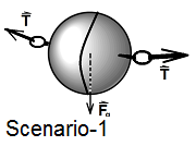
Event: Prior to the pull, the surrounding atmosphere pushes the half-shells together. As the hoirses pull, the contact force between the fitted shells diminishes. Should the horses have the strength, the contact force would diminish to zero, whereupon the shells would separate. Let the mass, diameter and shell thickness be m, D and t, respectively. Atmospheric ptessure is written patm and the pressure within the sphere after Otto's air pump removed air, is pins.
Derive: an expression for the least force to separate the hemispheres required of the horses.
♦ Analysis: We write Newton's 2nd Law, Eqn-1. Terms left-of-equality are zero since the momentum of the masses is constant. Scenario-1, an incomplete free-body-diagram, is drawn as a begining idea.
 |
(1) |
 |
The system is that matter contained within the half-cube.
Casual inspection of Scenario-1 reveals a system of the brass only would be tedious to tackle. To adopt that system would require us to deal with description of the outer, spherical surface of one hemispherical shell. We would need to sum the localized forces (pressure times area) over the sphere. This would be tedious. When a first idea of system proves awkward, select another. So let's try something!
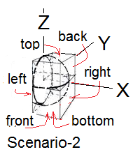
Scenario-2, shows our hemispherical half-shell (1/2 the sphere) placed inside of an imaginary half-cube. We label the faces of "half-cube" in coordinate pairs as "left and right (x-coord), "front and back (y-coord)" and "bottom and top (z-coord)." Ideally we would draw representations of pressure forces, gravity and tension on Scenario-2 thereby making it a free body diagram. Although graphical difficulty prevents further drawing, we can write the right side of Newton's 2nd Law. Upon the sphere act the forces of pull, represented as T, for tensions, each team of horses. All gravity forces act downward, (-K) and where there are gas at the boundary act pressure forces (pressure times area).

As a first simplification can we agree that the pressure distributions of atmospheric air over the front face and the back face are identical, whereupon the forces,
(patm-front x A) J + (patm-back x A(-J) = 0
sum to zero. With this fact our half-cube becomes two-dimensional. The list of forces for Newton's 2nd Law are written (Eqn-3). The 2-D system FBD is below right:
 |
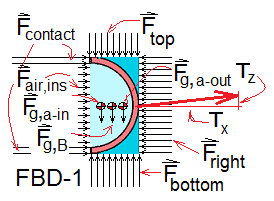 Notice the arrows of Ftop are
shorter than those of Fbottom. Why is that? |
A simpler, X-component perspective is possible. FBD-1 becomes FBD-2 when we select its 0XZ perspective. Also to multiply Eqn-3 by the unit vector I yields - Equation-4. To procede an understanding of areas of "left-face" is needed. See below left.
 |
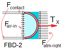 |

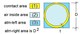
Acting over the square left-face of the system are: (1) the solid-solid contact force of the removed hemispherical brass shells, (2) gas-to-gas contact of the interior gas and (3) exterior, atmpspheric gas. These pressure-associated conditions of equilibrium act over a surface and are distributed. The effect at the brass-interface is similar to "pressure."
In display these are shown as many "arrows" directed perpendicular to the surface. The "arrows" represent localized forces being the product of the pressure over an elemental area of the related system surface times that area. The locations of gravity forces are at each "center of mass."
 |
(5) |
A re-cast of the next-to-last term is helpful.
 |
(6) |
Substitute (6) into (5) and align to show the addition.
 |
(7) |
With terms of (7) summed:
 |
(8) |
Applying some algebra:
 |
(9) |
Next we investigate a logical limit of Equation (9). For the realistic case that the shell thichness is much less than the shell diameter, the terms 4(t/D) and 4(t/D)2 are small and the rope x-component force becomes:
 |
(10) |
Tension ~ Z-component:
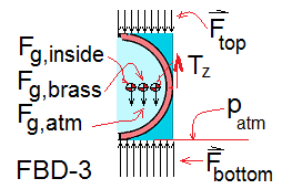 To inspect the vertical component, we extract FBD-3 from FBD-1 (shown right). The terms are a bit awkward to write.
 |
(11) |
Explicitly, the forces are mass times gravity or pressure times area.
 |
(12) |
For all of the forces we have:
 |
(13) |
The density of the brass is greatly larger than that of air inside or atmospheric air. Therefore we rearrange the first three terms as below. Also expand the next to last term.
 |
(14) |
From Eqn-10 we have the X-complnent of force of the horses. Eqn-13 is the Z-component. Adding (10) and (13) we obtain the vector force, T = TXI + TZTXI.
 |
(15) |
Now that the problem is over, did you see us apply the "Buoyancy Force?" That's the term rightmost in equation (15). When forces are summed properly, the "mass of fluid displaced" just "comes out in the wash."
Otto Von Guernike
German scientist, inventor and engineer.
At a fair in 1654 Otto amazed the spectators. He showed them two hemispherical brass shells that fit together (to form a hollow sphere) but fell apart when not held. Next, (using the air pump he invented) Otto removed air from the inside of the sphere. Each hemisphere had built-in ring to which a rope was attached. The other ends of the ropes were attached to harnesses of two teams of horses. The horses, urged to pull, strained and snorted but, to the surprise of everyone, they were unable to pull the hemispherical shells apart.
Premise presently unwritted!